Gestern haben wir kleine Aenderungen an einem M70 B12 mit Motronik 1.7 -352 vorgenommen.
Die Kettenraeder 11311718673 Steuertrieb-Steuerkette haben Laengsloecher
 RealOEM.com BMW E32 750iL Timing and valve train-timing chain
Gefunden haben wir diese Bilder, wo dargestellt wird, dass durch Laengung der Steuerketten sich die Ventiloeffnungs/-schliesswinkel aendern koennen. Ist relativ leicht zu korrigieren, wir haben 1 1/2 Tage gebraucht, weil ja oben alles ab muss. Und wir wollten uns Zeit lassen.
Text von 8Tech, Bilder sind von einem S70 Motor, Prozedur ist gleich:
HowTo-> Engine: Reset V12 Valve Timing.
Correct valve timing, or cam timing as some know it is very important for the smooth running of an engine and to extract the optimum performance from the engine. Just as ignition timing is set to produce the spark at the correct time, valve timing sets the valves to open and close at the correct time, both in relation to the crankshaft position.
This has become more and more important in recent years where extracting the very best efficiency from an engine has meant special timing tools for locking the engines on almost all new cars, whereas 20 years ago you set cambelt timing to the nearest tooth on the pulley/sprocket and only modified engines had adjustable aftermarket vernier pulleys to optimise the timing.
In the early 1980s, the hot mod was to slot the cam pulleys to allow us to optimise our timing on our drag bikes and guess what the E31 V12 has? Yep, slotted sprockets.
http://i283.photobucket.com/albums/k...w/IMG_0050.jpg
As you probably know, the crankshaft is connected to the cams through a chain and during 2 revolutions of the crank, each cam rotates once, at exactly the correct time, well almost. Assuming that the timing is exactly set correctly when the engine is assembled at the factory, as the chain stretches, the distance between the crank teeth and the cam sprocket teeth increases and this causes the valves to open and close too late due to a retarded camshaft.
Luckily, with slotted sprockets on the cams, we can rotate the cams on their sprockets to advance them back again to the correct position. To find this correct position for the cams, there is a pair of flats on each cam that is used with the appropriate cam locking tools, part nos C022 x 2 of
http://i283.photobucket.com/albums/k...IMG_0049-1.jpg
to set them in the correct position when the crank is at Top Dead Center (TDC).
You can find TDC either with the crank locking pin inserted between the back of the block and the flywheel, or as I did, by using the TDC mark on the front pulley. Using my method, you do not need to remove the timing chain tensioner to take up the chain slack.
http://i283.photobucket.com/albums/k...w/IMG_0041.jpg
Firstly, rotate the engine slowly using a 27mm socket on the front pulley bolt, in a clockwise (normal direction of rotation) direction.
http://i283.photobucket.com/albums/k...w/IMG_0044.jpg
This will cause the crank to pull the cams around taking up any chain slack. Continue until the TDC mark on the pulley approaches the timing mark on the front cover, and very slowly as you approach the marks aligning.
Stop when they are aligned. If you go too far, DO NOT GO BACKWARDS to align the marks, go around another complete crank revolution. If you went backwards, the tension on the chain will be on the wrong side and the timing will be miles out.
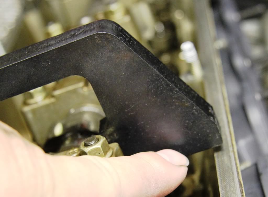
With the crank now at TDC, slide the timing tools on the cams and see if they sit flush with the head face. If not, as seen here, the timing needs to be reset.
http://i283.photobucket.com/albums/k...w/IMG_0042.jpg
http://i283.photobucket.com/albums/k...w/IMG_0043.jpg
There are 6 x 10mm bolts holding each cam to its sprocket, and with the engine set as it is you can slacken off the top 3 on each cam.
http://i283.photobucket.com/albums/k...w/IMG_0045.jpg
Now remove the timing tools and rotate the crank clockwise 1 revolution again and as before, bring the timing mark on the crank pulley to approach the timing mark on the front cover. Now refit the timing tool on the cam of cylinders 7-12 as shown. SLOWLY rotate the crank until the tool sits correctly on the head.
http://i283.photobucket.com/albums/k...w/IMG_0040.jpg
Now slacken the top 3 bolts on the cylinder 7-12 cam so that all 6 are now loose on that cam.
SLOWLY rotate the crank BACKWARDS (anti-clockwise), watching the sprocket rotate on the locked cam until the bolts are almost at the ends of their slots. Look at the timing marks on the crank pulley and front cover and you should be to the left of the cover mark with the pulley mark.
http://i283.photobucket.com/albums/k...IMG_0047-1.jpg
Now slowly rotate the crank as before (clockwise) until the timing marks align. With the timing marks aligned and the tool still locking the cam in position, tighten the top 3 sprocket bolts on that cam.
You can now remove the timing tool and repeat the procedure for the cyl 1-6 cam, exactly as before, locking up the top 3 sprocket bolts again
http://i283.photobucket.com/albums/k...IMG_0046-1.jpg
Now, with the cams correctly timed, rotate the crank 1 full revolution which will expose the remaining 3 loose bolts on each sprocket which can now be tightened.
You can finally rotate the crank once more and setting the timing marks up correctly, you should be able to fit the cam timing locking plates flush with the head. If so, then your cam timing is now correct.
http://i283.photobucket.com/albums/k...IMG_0037-1.jpg
There are a few assumptions made in this procedure and that is that the flats on the camshafts and the position of the TDC mark is accurate. For almost all cases, these are perfectly adequate for the purposes of setting cam timing but for the true perfectionist, a degree wheel would be used on the front pulley with a micrometer dial gauge used to find true TDC, and the valves would be set using a dial gauge on the cam lobes to accurately set the cam position.
NOTE: All pics taken with cam oil spray bars removed for clarity. 8Tech.
----------------------------
Und so aehnlich wi in seinem Bild war auch am B12 die Zeit nicht mehr richtig gestellt, war ein Spalt beim Messen aehnlich wie hier, rechts sieht man es